Aerogenerator Board communication driver
Aerogenerator Board Communication Driver is the driver to communicate with 50KW Aerogenerator Board of Taechang ENT in Korea.
1. Read settings
<Figure 1> is Aerogenerator Board communication driver’s read setting examples.
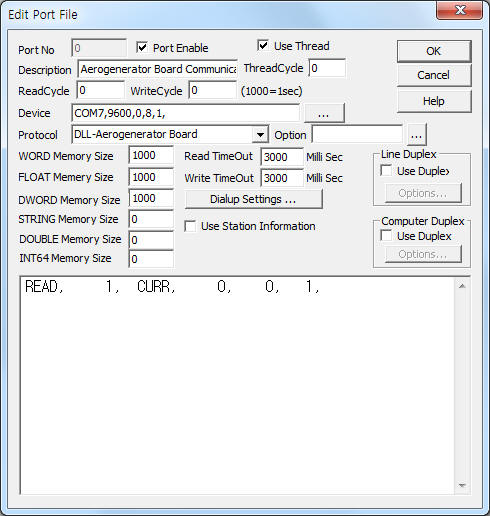 |
| <Figure 1> Aerogenerator Board communication driver’s read setting examples |
<Figure 1> is the screen where Com Port(COM1), Baud Rate(9600), Parity Bit(0), Data Bit(8), Stop Bit(1) are input in DEVICE.
Aerogenerator Board communication driver’s read schedule
Read schedule setting parameters are as follows:
1) STATION – Input 0 ~ 255 ID No.
2) Read command – command = CURR . (refer to <Table 1>)
3) Read Data Start Position - Don't care.
4) Save Start Address for Communication Server – Input save start address of communication server.
5) Read Size – Fixed the read size = 1.
Read schedule example)
READ, 1, CURR, 0, 0, 1,
<Table 1> is a description of CURR read command,s stored values of Aerogenerator Board communication driver.
| Read Command | Content | Store Values |
| CURR | read current status | Start Addr + 0 ~ 3 : Pressure 1 ~ 4 Start Addr + 4 : RPM Start Addr + 5 : Vibration DB Start Addr + 6 : Temperature DB Start Addr + 7 : Generator Temperature Start Addr + 8 : Magnetic Brake Temperature Start Addr + 9 : Encorder (WORD) Start Addr + 10 ~ 11 : Slope 1 ~ 2 Start Addr + 12 : Wind Directions(WORD) Start Addr + 13 : Wind Speed(WORD) Start Addr + 14 : Current Temperature Start Addr + 15 : Vibration YAW Start Addr + 16 : Contact Status Start Addr + 17 : Voltage Start Addr + 18 : Current Start Addr + 19 : Magnetic Brake Level Start Addr + 20 : Current Power(KW) Start Addr + 21 : Error Start Addr + 22 : Wind Speed absolute value (WORD) |
| <Table 1> CURR read command,s stored values of Aerogenerator Board communication driver. | ||
If you click the icon  in
protocol option part, you can see the dialogue box such as <Figure 2>. you can
also set read schedule by using this part.
in
protocol option part, you can see the dialogue box such as <Figure 2>. you can
also set read schedule by using this part.
 |
| <Figure 2> Example of Aerogenerator Board communication driver’s Option dialogue box |
You can set read schedule by using
 ,
,
 ,
,
 button
and listbox of <Figure 2>.
button
and listbox of <Figure 2>.
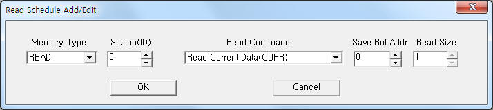 |
| <Figure 3> Example of Aerogenerator Board communication driver’s read schedule Add/Edit dialogue box |
When you click Add button or Edit button in dialogue box of <Figure 2>, dialogue box of <Figure 3> is shown.
2. Writing settings
You can control Aerogenerator Board by using write commands.
Bit Write
Bit write setting parameters are as follows:
1) PORT Port no. (0 ~ 255)
2) STATION Input 0 ~ 255 ID No.
3) ADDRESS Don't care.
4) Extra1 write command = STOP, PR1, PR2, PR3, PR4, MORTOR, YAW_L, YAW_R, YAW_S, RESET, SPARE1, SPARE2. (refer to <Table 2>)
5) Extra2 Don't care.
<Table 2> is a description of Write command type and content of Aerogenerator Board communication driver.
| Write Command | Content | Output Value |
| STOP | forcing stop/release command | 10 = Forcing Stop, 0 : Forcing Release |
| PR1, PR2, PR3, PR4 | disk brake control, pressure 1 ~ 4 | 1 : Pressure ON, 0 : Pressure OFF |
| MORTOR | disk brake mortor control | 1 : Mortor ON, 0 : Mortor OFF |
| YAW_L | YAW left control | Don't care |
| YAW_R | YAW right control | Don't care |
| YAW_S | YAW stop command | Don't care |
| RESET | main board reset command | Don't care |
| SPARE1, SPARE2 | Spare1 ~ 2 On/Off command | 1 : Spare 1 ~ 2 ON, 0 : Spare 1 ~ 2 OFF
|
| <Table 2> Write command type and content of Aerogenerator Board communication driver. | ||
Word Write
Word write and bit write have the same setting parameters except output value.
Write example 1)
PORT : 0 STATION : 1 ADDRESS : 0010 EXTRA1 : STOP EXTRA2 : 0
The setting parameter shown above is an example of bit write for forcing stop(ON)/release(OFF) command.
Write Example 2)
PORT : 0 STATION : 0 ADDRESS : 0200 EXTRA1 : PR1 EXTRA2 : 0
The setting parameter shown above is an example of bit write for disk brake control, pressure 1 command.
Block Write
Aerogenerator Board communication driver don’t support ‘Block write’.
3. Serial cable connection of Aerogenerator Board
You have to connect serial communication cable in the following ways.
Connection of serial communication cable
You can connect RS-485 communication cable to terminal A, B of Aerogenerator Board( J75) and PC Respectively.
<Figure 4> shows the appearance of Aerogenerator Board equipment.
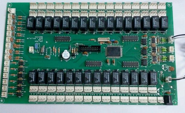 |
| <Figure 4> Appearance of Aerogenerator Board equipment |